Fiber Optic Quartz: A Complete Guide to Preforms, Substrate Tubes & the Draw Tower
Every strand of optical fiber on the planet began as a thick rod of ultra-pure fused silica called a preform — and that preform was built inside, or around, a quartz tube. This guide explains how fiber optic quartz products turn into glass thinner than a human hair, why a few parts per billion of the wrong impurity can ruin a kilometre of fiber, and what makes a substrate tube fit for the job.
Optical fiber is the most demanding purity application that fused silica is used in. A signal travelling down a long-haul fibre passes through tens of kilometres of glass before it is regenerated, so the glass has to be transparent to a degree that is hard to imagine — losing only a tiny fraction of the light per kilometre. The only material that can do this is ultra-high-purity synthetic fused silica, and the components that make it are quartz tubes and rods.
Fiber optic quartz products — substrate tubes, overcladding (jacketing) tubes, handle and starting rods, and support hardware — are where the optical path of every fibre is born. Their purity, hydroxyl (OH) content, geometric precision and freedom from bubbles and striae carry straight into the attenuation, bandwidth and mechanical strength of the finished fibre.
This guide walks through the whole chain: what each fiber optic quartz product does, how the major preform processes use them, why purity and geometry decide fibre loss, and what is driving demand as AI data centres reshape the optical-fibre market.
This guide covers the high-purity quartz consumables used to make optical-fibre preforms — substrate tubes, overcladding and handle tubes, and starting rods — and how they feed the draw tower. It does not cover the draw-tower coating chemistry, cabling, or connector hardware, where quartz is not the working material.
01 — The Preform, the Substrate Tube, and Why Purity Rules Everything
A preform is a scaled-up glass model of the finished fibre: a rod, typically tens of millimetres across and around a metre long, that already contains the fibre’s complete refractive-index profile — a higher-index core surrounded by a lower-index cladding. When that rod is heated and drawn, every internal proportion is preserved as it stretches into kilometres of fibre. Get the preform right and the fibre is right; get it wrong and no amount of downstream processing can fix it.
That index profile is created with doped fused silica — pure silica for the cladding, silica lightly doped (commonly with germanium) to raise the index for the core. The host material in every case is fused silica, because nothing else combines the transparency, the attainable purity, and the high-temperature workability that fibre demands.
Why hydroxyl (OH) content is the defining parameter
The single property that separates fibre-grade fused silica from ordinary fused quartz is hydroxyl content. OH groups in the glass absorb light strongly in the near-infrared — the well-known “water peak” around the 1383 nm region — exactly where telecom fibre wants to operate. For low-loss telecom and long-haul fibre, the silica that becomes the optical path must have extremely low OH; for some specialty and UV-guiding fibres, by contrast, high-OH glass is deliberately chosen. OH content is therefore not a single “better is lower” spec — it is a design choice that the quartz must be matched to.
Alongside OH, metallic impurities at the parts-per-billion level matter: transition metals create absorption that scales straight into fibre attenuation. This is why the parts that become the optical path are made from synthetic fused silica, produced from chemically purified precursors rather than melted natural sand.
The substrate tube: where the fibre is born
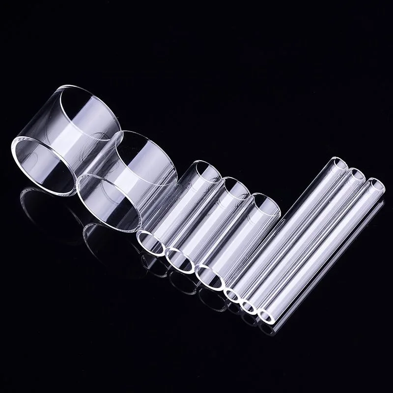
In the most widely used inside-deposition processes, a fused silica substrate tube is the vessel inside which the core and inner cladding are built up, layer by layer, before the tube is collapsed into a solid rod. Because the substrate tube becomes part of the finished fibre, its requirements are severe: ultra-controlled OH, parts-per-billion metallic purity, freedom from bubbles and striae (internal index streaks), and tight geometry — straightness, roundness, and uniform diameter and wall thickness along the full length. A bubble or inclusion that survives into the preform becomes either an attenuation source or the point where the fibre snaps during draw.
Any ovality or wall-thickness variation in the substrate tube distorts the index profile and shifts the core off-centre. In the finished fibre that shows up as core-to-cladding concentricity error, which raises splice loss every time two fibres are joined. A tube that is pure but geometrically sloppy still ruins the fibre — purity and precision are equally non-negotiable here.
02 — The Complete Fiber Optic Quartz Product Ecosystem
Preform fabrication uses several distinct quartz products, and which ones appear depends on the deposition route. Here is the full set and the job each one does.
| Product | Role in preform making | Becomes part of the fibre? | Critical requirement |
|---|---|---|---|
| Substrate tube | Inner vessel for MCVD/PCVD deposition; collapses into the core rod | Yes — forms part of the cladding | Ultra-low OH, ppb-level purity, no striae/bubbles, tight geometry |
| Overcladding (jacketing) tube | Large tube collapsed over the core rod to add cladding glass and reach final preform size | Yes — the outer cladding | Synthetic-grade purity and high concentricity; large bore with uniform wall |
| Handle / dummy tube | Welded to the preform end to hold and feed it through deposition, collapse and draw | No — sacrificial / reused | Straightness, clean weldability, thermal stability; can be natural fused quartz |
| Starting / target rod (OVD & VAD) | Bait/seed that soot is deposited onto; removed (OVD) or grown from (VAD) | No (OVD) / seed (VAD) | Dimensional consistency and a clean, particle-free surface |
| Sleeve / extension tube | Joins, extends or protects preforms between process steps | Sometimes | Matched diameter and clean fusion to avoid trapped interfaces |
| Support & furnace hardware | Holders, spacers and liners around deposition and draw stations | No | High-temperature stability and low contamination shedding |
Not every quartz part in fibre making has to be synthetic ultra-pure. The parts that become the optical path (substrate and overcladding tubes) carry the strictest spec; handle tubes, starting rods and support hardware are held to geometric and thermal standards but can use high-quality natural fused quartz. Matching the right grade to each role is where cost and performance are balanced — FGQuartz can supply both tiers, including custom quartz glass to your drawing.
03 — How the Quartz Products Build a Fibre, Step by Step
Route A · Inside deposition — MCVD and PCVD (substrate tube)
What happens: a substrate tube is mounted on a glass-working lathe and rotated while reactant gases (a silicon precursor plus dopants and oxygen) flow through its bore. A heat source traversing the outside — an oxy-hydrogen torch in MCVD, a microwave plasma in PCVD — drives the reaction, depositing fine doped glass soot on the inner wall that sinters into a clear layer with each pass. Hundreds of passes build the precise index profile from cladding inward to core. The tube is then heated further and collapses inward into a solid core rod.
What the quartz delivers: the substrate tube’s bore geometry sets how uniformly each deposited layer lands, and its purity and OH carry directly into the cladding glass of the fibre. Because the deposition runs at high temperature for a long time, the tube must hold its straightness and roundness throughout — any sag becomes index distortion. This route is the workhorse for single-mode telecom and many specialty fibres.
Route B · Outside & axial deposition — OVD and VAD (rods & mandrels)
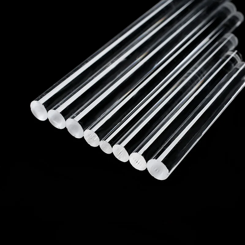
What happens: instead of depositing inside a tube, OVD builds soot on the outside of a rotating starting rod (later removed), and VAD grows a soot body axially from the end of a rotating seed. The porous soot body is then dehydrated — a critical step that strips out OH — and sintered into a clear glass preform.
What the quartz delivers: here the fused silica rods and mandrels are tooling, not optical path, so their job is dimensional consistency and a clean surface that lets the soot build and release predictably. The dehydration and sintering steps do the OH control, but a poor-quality mandrel that sheds particles or runs out of true still ruins the soot body. These routes scale well to very large preforms, which is why they dominate high-volume single-mode production.
Step C · Overcladding — reaching final preform size
What happens: a core rod usually does not carry enough cladding glass on its own, so cladding is added — most commonly by collapsing a large overcladding tube over the core rod (rod-in-tube), or by depositing additional soot. This brings the preform to its final core-to-clad ratio and overall diameter.
What the quartz delivers: the overcladding tube becomes the outer cladding of the fibre, so it needs synthetic-grade purity and, above all, excellent concentricity and wall uniformity — because any eccentricity here directly offsets the core in the final fibre and raises splice loss. As the industry pushes to larger preforms for cost efficiency, overcladding tubes have grown to large diameters while still holding tight geometry, which is a serious manufacturing challenge.
Step D · Drawing the fibre
What happens: the finished preform, held by its handle tube, is lowered into the top of a draw-tower furnace and heated until the tip softens and a fine strand pulls away under gravity. Feedback control adjusts feed and draw speed to hold the fibre diameter constant as kilometres are drawn, coated and wound. The temperatures here sit in the range where only fused silica survives as a forming material.
What the quartz delivers: by this stage the optical quartz has already done its defining work — the draw faithfully reproduces whatever the preform contains. The handle tube must feed the preform smoothly and stay stable at temperature; any wobble or off-centre feed translates into diameter and geometry variation in the fibre. For the high-temperature furnace environment, see also high-temperature quartz.
04 — Why Purity and Geometry Decide Fibre Loss
Fibre performance is unforgiving because the light travels so far through the glass. A defect that would be invisible in a lens or a window becomes a measurable loss over kilometres. Here is how each quartz property maps onto a fibre outcome.
| Quartz property | Fibre consequence if out of spec |
|---|---|
| Hydroxyl (OH) content | Excess OH creates the near-infrared water-peak absorption, raising attenuation precisely in the telecom operating window |
| Metallic impurities (ppb level) | Transition metals absorb across the transmission band, adding loss that accumulates over every kilometre of fibre |
| Bubbles & inclusions | Scatter light and act as mechanical flaws — the most common origin of fibre breaks during high-tension drawing |
| Striae (index streaks) | Local refractive-index variation distorts the guided mode and degrades bandwidth and loss |
| Ovality & wall variation | Distorts the index profile and offsets the core, producing core-cladding concentricity error and higher splice loss |
| Straightness / high-temp stability | A tube that sags during long deposition warps the profile and can render an entire preform unusable |
Every flaw in the preform is amplified by the draw ratio. A preform is drawn into many kilometres of fibre, so a single small inclusion or a fraction of a percent of eccentricity is stretched along the entire run. This is why fibre quartz is qualified to a far tighter standard than quartz for almost any other use — there is no inspection step after the draw that can remove a defect built into the preform.
05 — Qualification, and the Synthetic-vs-Natural Divide
Qualifying a fibre-grade tube goes well beyond a dimensional check. A typical evaluation covers OH content by infrared absorption, metallic impurity analysis at trace levels, bubble and inclusion inspection, striae and homogeneity assessment, full dimensional mapping (diameter, wall, ovality, straightness along the length), and ultimately a trial preform and draw that compares the resulting fibre’s attenuation, geometry and strength against the incumbent supply. A tube earns volume status only after it produces fibre that meets the customer’s loss and geometry targets repeatably.
Synthetic where it counts, natural where it can
The defining material decision in fibre quartz is synthetic versus natural fused silica. Synthetic fused silica is made from chemically purified precursors, which allows the parts-per-billion metallic purity and the controlled OH that the optical path requires — so substrate and overcladding tubes that become the fibre are synthetic-grade. Natural fused quartz, melted from high-purity sand, is more economical and entirely suitable for handle tubes, starting rods and support hardware that never carry light. Specifying synthetic everywhere wastes money; specifying natural in the optical path ruins the fibre. The skill is in drawing the line correctly for each component.
Market structure
Tier 1 — a small group of global synthetic fused silica producers supply the highest-grade substrate and overcladding tubes for premium low-loss telecom fibre, backed by deep process data with the major fibre makers. Tier 2 — capable manufacturers serving the large mid-market for standard single-mode fibre tubes, support tooling and natural-quartz components, increasingly competitive on synthetic grades. Tier 3 — suppliers of handle tubes, rods and support hardware where geometry and thermal stability matter but optical-path purity does not.
06 — Consumed, Sacrificial, or Reused
Fibre quartz splits cleanly into three lifecycle types, and managing each correctly controls both cost and quality.
Consumed into the fibre. Substrate and overcladding tubes do not come back — they become the cladding of the fibre. Their “lifecycle” is really a quality question: each one must be inspected and qualified before use, because a flaw is locked into product the moment the preform is built. There is no reclaim, only prevention.
Sacrificial / limited reuse. Handle and dummy tubes are welded on, used through the campaign, and trimmed or replaced as their ends are consumed by repeated fusion. They are inspected for straightness and clean weld surfaces and retired when they can no longer feed the preform true.
Reused tooling. Starting rods, mandrels and support hardware are cleaned and re-run many times. They follow the familiar discipline: scheduled cleaning, dimensional checks, surface inspection for particle-shedding wear, and replacement when they run out of true or begin generating contamination. Keep them free of the metallic contamination that would transfer to a soot body.
07 — Fibre Quartz in the Supply Chain
Synthetic fused silica tubing for fibre sits at the top of the quartz purity pyramid, and its supply is concentrated among a handful of producers with the precursor chemistry and tube-forming know-how to hit fibre grade consistently. That concentration makes the tube a strategic input: when fibre demand surges, synthetic tube capacity is one of the first constraints the industry hits, and tube availability can gate how fast fibre output can grow.
Natural fused quartz handle tubes, rods and support hardware are far more broadly available, which is why separating the synthetic optical-path parts from the natural tooling parts matters commercially as well as technically — it lets fibre makers concentrate their scarce, expensive synthetic supply only where it actually changes the fibre, and source the rest competitively. As with the rest of the quartz world, the value is in conversion know-how, not in owning silica.
08 — Where Fibre Optic Quartz Is Going
1 · AI data centres are reshaping demand. The build-out of AI compute has driven a steep rise in data-centre interconnect fibre, on top of continuing FTTH and long-haul growth. More fibre means more preforms, and more preforms means sustained pull on synthetic substrate and overcladding tubes — keeping tube supply a watch-item for the whole industry.
2 · Larger preforms for lower cost. Drawing more fibre from each preform is the main lever for cost reduction, so preforms keep growing — which pushes overcladding tubes to larger diameters while demanding the same tight concentricity. Making big tubes that are still geometrically perfect is an increasingly important capability.
3 · Hollow-core and specialty fibre. Hollow-core fibre, which guides light largely in air for lower latency, and a widening range of specialty fibres for sensing and fibre lasers, call for new and often more intricate quartz tube geometries — moving the quartz supplier further into co-design.
4 · Tighter OH and geometry control. As loss budgets tighten and geometries shrink, the OH and dimensional specifications on fibre tubes keep ratcheting down, rewarding suppliers who can measure and hold those parameters run after run.
09 — Frequently Asked Questions
What is a substrate tube in optical fibre manufacturing?
A substrate tube is a high-purity fused silica tube used as the vessel for inside-deposition preform processes such as MCVD and PCVD. Reactant gases flow through its bore while a heat source outside drives the reaction, depositing doped glass layers on the inner wall that build the fibre’s refractive-index profile. The tube is then collapsed into a solid core rod. Because the substrate tube becomes part of the finished fibre’s cladding, it must have ultra-controlled OH, parts-per-billion metallic purity, no bubbles or striae, and tight geometry.
Why does hydroxyl (OH) content matter so much for fibre?
OH groups in fused silica absorb light strongly in the near-infrared — the “water peak” near the 1383 nm region — which overlaps the telecom transmission window. For low-loss telecom and long-haul fibre, the silica that becomes the optical path must therefore have extremely low OH. Some specialty and UV-guiding fibres deliberately use high-OH glass instead. OH is not simply “lower is better”; it is a design parameter that the quartz grade must be matched to for the intended fibre.
What is the difference between MCVD, OVD and VAD?
They are three routes to the same goal — a preform with the right index profile. MCVD (and its plasma variant PCVD) deposits glass on the inside of a rotating substrate tube. OVD deposits soot on the outside of a starting rod, which is later removed. VAD grows a soot body axially from a rotating seed. Inside deposition uses a substrate tube that becomes the fibre; the outside and axial routes use fused silica rods and mandrels as tooling and rely on a separate dehydration and sintering step for OH control. OVD and VAD scale to very large preforms, which suits high-volume single-mode production.
What is an overcladding tube and why is its geometry critical?
An overcladding (jacketing) tube is a large fused silica tube collapsed over a core rod to add cladding glass and bring the preform to its final size — the rod-in-tube method. Because it becomes the outer cladding of the fibre, it needs synthetic-grade purity and, critically, excellent concentricity and wall uniformity. Any eccentricity in the overcladding tube offsets the core in the finished fibre, producing core-to-cladding concentricity error that raises loss every time the fibre is spliced.
When is synthetic fused silica required, and when is natural quartz enough?
Use synthetic fused silica for the parts that become the optical path — substrate and overcladding tubes — because only chemically purified synthetic material reaches the parts-per-billion purity and controlled OH that low fibre loss demands. Natural fused quartz, melted from high-purity sand, is more economical and fully suitable for handle tubes, starting rods and support hardware that never carry light. Specifying synthetic for every part wastes money; using natural quartz in the optical path ruins the fibre.
How does a defect in the quartz tube affect the finished fibre?
It is amplified by the draw. A preform is stretched into many kilometres of fibre, so a single bubble, inclusion or fraction of a percent of eccentricity is spread along the entire drawn length — as a scattering loss, an attenuation source, or a geometry error that raises splice loss. Worse, bubbles and inclusions act as mechanical flaws that cause the fibre to break under draw tension. There is no post-draw step that can remove a defect built into the preform, which is why fibre quartz is held to a tighter standard than almost any other quartz application.
Sourcing Quartz Tubes & Rods for Fibre Production?
FGQuartz manufactures high-purity fused silica tubes and rods, and custom fibre tooling, from our works in Lianyungang, China, shipped worldwide. For the commercial range and request-a-quote details, see our fiber optic quartz application page, browse quartz tubes and quartz rods, explore related optical quartz glass, or view our full product range and application library.