Semiconductor Quartz Products: A Complete Guide to Boats, Tubes & Thermal Process Integration
Most people in the industry treat quartz boats as standard consumables — interchangeable, low-tech, easy to procure. They’re wrong. This guide breaks down exactly how every quartz product works inside a semiconductor fab, why the design details matter far more than most engineers realize, and what happens to yield when any part of the system is mismatched.
There’s a moment that most process engineers encounter at least once in their careers: you’ve spent weeks chasing a mysterious yield loss across your thermal oxidation line. You’ve checked the gas purity. You’ve verified the temperature controller. You’ve swapped the thermocouple. Nothing works. Then someone suggests checking the quartz boat — and you discover it has thermally deformed by less than a millimeter. That’s it. That was the entire root cause.
Semiconductor quartz products — boats, furnace tubes, gas nozzles, flow baffles, thermocouple sleeves — form the physical infrastructure inside every high-temperature furnace in the fab. Their geometry, purity, surface finish, and fit with each other directly shape the thermal field, gas flow distribution, and mechanical precision that determine whether a process hits its target or drifts into the reject zone.
This guide covers everything: what each quartz product does, how they work as a coordinated system through each thermal process step, why advanced process nodes demand so much more from these components, and what the practical rules are for qualification, maintenance, and lifecycle management.
This guide covers high-temperature thermal process applications only — thermal oxidation, diffusion doping, LPCVD, post-implant annealing, and 3D stacking anneal. It does not cover PECVD, PVD, wet clean, or CMP, where quartz products either aren’t used or play a fundamentally different role.
01 — What Is a Semiconductor Quartz Boat, and Why Does It Matter?
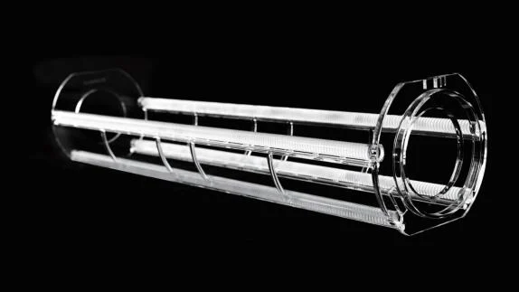
A semiconductor quartz boat is a wafer-carrying fixture made from electronic-grade high-purity fused silica (synthetic amorphous silicon dioxide). It holds wafers vertically or at a slight tilt inside a furnace tube during high-temperature processing, keeping them evenly spaced, stable, and in the right orientation relative to the gas flow and heat source.
That description sounds simple. But the design engineering that goes into a production-grade quartz boat — particularly for advanced nodes — is anything but. Every geometric feature of the boat participates in shaping the environment each wafer experiences during processing.
Why fused silica, specifically?
Fused silica (amorphous SiO₂) has a set of properties that make it uniquely suited to semiconductor thermal processing:
| Property | Why It Matters in the Furnace | Consequence of Inadequate Quality |
|---|---|---|
| Ultra-low thermal expansion | The boat keeps its geometry from room temperature to process temperature, holding every wafer slot in the same position relative to the robotic arm and gas nozzles | Thermal deformation causes slot displacement, wafer tilt, pick-and-place errors, and potential wafer-to-wafer contact |
| Extreme high-temperature stability | The boat structure does not soften, creep, or lose mechanical integrity at process temperatures | Creep deformation leads to asymmetric loading on the wafer, uneven heat exposure, and bowing |
| Excellent chemical inertness | The boat does not react with oxidizing, reducing, or halide-based process gases, and does not contribute metallic or organic impurities to the wafer surface | Any reaction or outgassing introduces contamination that degrades device leakage, threshold voltage, and reliability |
| High infrared transmittance | Radiant heat passes through the boat walls and supports, reaching wafer surfaces directly from the heating elements | Opaque or poorly transmissive material creates thermal shadowing and wafer-to-wafer temperature variation |
| Ultra-high purity (electronic grade) | Metallic impurity content is controlled to trace levels that won’t affect device-level electrical performance | Trace metallic contamination can introduce deep-level traps in the device oxide, degrading reliability and threshold stability |
The four functional modules of a quartz boat
Every quartz boat, regardless of size or process type, is built from the same four functional modules — and the engineering of each one drives the process outcome:
- Slot teeth (wafer contact points) — the curved features that support each wafer by its edge. Tooth width, radius, contact angle, surface finish and pitch determine wafer stability, contact area, thermal conduction from the wafer edge, and particle generation from edge friction.
- Support rods — the three or four longitudinal rods that run the full boat length and carry all mechanical load. Their straightness, diameter and high-temperature creep resistance determine whether the boat stays aligned after hundreds of thermal cycles.
- End plates — the discs at each end that anchor the support rods. End-plate flatness sets the boat’s vertical alignment, and the weld joint between end plate and rod is the highest-stress location — the most common failure point under repeated cycling.
- Flow guide structures — optional but important in advanced designs: slots, chamfers, open sections or deflector fins added to direct gas flow across each wafer slot. These are matched to the nozzle hole pattern and differ by process type.
The flow guides on an oxidation boat are designed for an oxidizing atmosphere at near-atmospheric pressure. An LPCVD boat operates at low pressure with reactive CVD precursors. A diffusion boat handles dopant carrier gases with different flow dynamics. A quartz boat is therefore never a generic, interchangeable component — it is always process-specific.
02 — The Complete Semiconductor Quartz Product Ecosystem
The quartz boat is not a standalone piece of equipment — it’s one component in an interconnected system of quartz products that together define the entire thermal process environment. Understanding how these products relate to each other is essential for troubleshooting process excursions and for qualifying new hardware.
| Category | Product | Primary Function | Coupling with the Quartz Boat |
|---|---|---|---|
| Wafer Bearing | Quartz Boat | Holds wafers at defined positions inside the furnace tube | Primary reference component |
| Wafer Bearing | Quartz Boat Stand | Interface between the boat and the furnace drive mechanism; carries the boat in and out of the tube | Tolerance must match the boat’s thermal expansion to prevent relative slip at temperature |
| Wafer Bearing | Quartz Wafer Transfer Fork | Robotic end effector for moving wafers from cassette to boat slots | Fork geometry must match slot pitch precisely and must not scratch the wafer edge or generate particles |
| Wafer Bearing | Quartz Cleaning Basket | Transports and immerses the boat in acid/base cleaning baths | Must hold the boat without contact pressure on support rods or end plates |
| Wafer Bearing | SiC Composite Boat | High-performance variant with SiC coating or SiC support rods for extreme creep resistance | Drop-in upgrade when standard quartz boats hit their creep or particle limits at advanced nodes |
| Chamber Body | Quartz Furnace Tube | The reaction chamber itself; the boat sits inside it | Inner diameter must provide a uniform annular gas-flow gap around the loaded boat |
| Chamber Body | Quartz Bell Jar | Upper chamber closure on some vertical annealing furnaces; provides a radiant heat enclosure | IR transmittance uniformity determines how evenly heat reaches all wafer positions |
| Chamber Body | Quartz Insulation Cylinder | Sleeve between the tube wall and heating elements; reduces heat loss and stabilizes the axial temperature profile | Temperature-field stability sets batch-to-batch consistency for every wafer on the boat |
| Gas Distribution | Quartz Gas Inlet Nozzle | Injects process gas at the tube inlet and distributes it across the boat length | Hole pattern and pitch are co-designed with the boat’s slot pitch and flow guides |
| Gas Distribution | Quartz Flow Baffle | Breaks up the incoming gas jet so no single wafer sees disproportionate flow | Hole pattern matched to the boat’s front-end geometry and the target velocity profile |
| Gas Distribution | Quartz Exhaust Tube | Carries process by-products and exhaust gases cleanly out of the tube | A smooth bore prevents by-product build-up that could fall as particles onto the boat |
| Process Auxiliary | Quartz TC Sleeve | Protects the thermocouple from process gas while allowing accurate temperature measurement | Measurement accuracy determines the temperature control every wafer experiences |
| Process Auxiliary | Quartz Calibration Block | Reference piece from the same material batch as the boat, used for dimensional verification | Provides the go/no-go reference for slot-position and straightness inspection |
In a properly engineered thermal process line, the quartz boat, furnace tube, gas nozzle and flow baffle are co-designed and co-qualified as a matched set. Replacing any one component with a part from a different manufacturer — even one with nominally identical specifications — can disturb the gas flow or temperature uniformity the rest of the system was tuned around. FGQuartz can supply these as a coordinated set; talk to us about custom quartz components made to your drawing.
03 — How Quartz Products Work Together Across Every Thermal Process Step
Now let’s follow a wafer through the thermal process module from start to finish — watching each quartz product come into play, understanding its specific design requirements for that step, and seeing how the products interact to produce the intended result.
Step 1 · Thermal Oxidation — the first thermal step
Purpose: grow a controlled-thickness layer of silicon dioxide on the wafer in an oxygen or steam ambient. This oxide serves as gate dielectric, field isolation, or passivation depending on where it sits in the device stack. Thickness uniformity across the wafer and batch ties directly to transistor threshold-voltage consistency.
Quartz products active in this step: transfer fork (loads wafers from the FOUP without edge contact), oxidation boat (slot geometry tuned for atmospheric-pressure oxidant flow), boat stand, furnace tube (smooth inner wall prevents oxide-flake contamination), insulation cylinder, gas nozzle (distributes O₂ or H₂O+O₂ across all positions), flow baffle, TC sleeve, exhaust tube, and cleaning basket.
How the system works: the transfer fork picks wafers and places them into the boat’s pre-designated slots — the fork’s geometry mirrors the slot pitch exactly, since any mismatch causes misaligned loading. The loaded boat lowers onto the boat stand, dimensionally matched so thermal expansion during ramp-up doesn’t cause relative sliding that generates SiO₂ particles. Inside the tube, the nozzle and baffle deliver a uniform oxidant flow while the insulation cylinder and TC sleeve hold the axial temperature profile flat across the whole boat length. After the run, by-products vent through the exhaust tube and the boat is supported in a cleaning basket for its wet-clean cycle.
Step 2 · Thermal Diffusion Doping — electrical property formation
Purpose: drive boron, phosphorus, arsenic or other dopants into the silicon lattice to defined depths and concentrations, forming p-n junctions, wells and source/drain extensions. Dopant concentration uniformity defines threshold voltage and leakage-current uniformity — among the most direct drivers of parametric yield.
Why the diffusion boat differs from the oxidation boat: its slot design is optimized for the dopant carrier flow pattern, its interior is passivated to minimize dopant wall adsorption, its flow guides are matched to dopant-source delivery dynamics, and it carries a strict cross-contamination control regime with an extended post-run clean and particle verification before re-use.
How the system works: the diffusion boat is a purpose-built, process-dedicated component — never shared with oxidation or LPCVD lines (the fork should be dedicated too, since a fork used in a phosphorus line then a boron line carries residues across). The furnace tube receives a pre-process passivation treatment so dopant atoms don’t adsorb into the quartz and later re-release during other runs — a slow contamination mechanism often misdiagnosed as a gas-purity issue. The dopant source enters through a multi-zone nozzle (independent flow control for each third of the boat length) that compensates for natural depletion from inlet to exhaust, so wafer 1 and wafer 150 receive equivalent flux. A deformation-induced tilt of even a fraction of a degree changes a wafer’s face angle to the gas flow and creates a within-wafer dopant gradient.
Diffusion quartz boats must never be used in any other process line. Residual dopants — especially heavy species like arsenic — can survive standard cleaning cycles and contaminate the next batch. Fabs with unexplained junction-depth variation or leakage excursions have traced the cause to boat cross-use surprisingly often. Physical color-coding and RFID tagging of boats by process family is strongly recommended.
Step 3 · LPCVD — Low-Pressure Chemical Vapor Deposition
Purpose: deposit functional thin films — polysilicon, silicon nitride, silicon oxide and other dielectrics — with high thickness uniformity. These become gate electrodes, spacers, hard masks and barrier layers. LPCVD remains essential for conformal step coverage in high-aspect-ratio structures even as ALD has taken over the very thinnest layers.
Why LPCVD demands the most from quartz products: first, it operates at lower pressure, so molecular flow dominates and gas distribution relies on design geometry more than mass flow rates. Second, CVD by-products deposit on everything in the chamber — including the boat and tube interior — and will eventually flake off as particles if not managed. Third, the higher wafer-loading density used to maximize throughput intensifies both thermal shadowing and boundary-layer depletion.
LPCVD-specific quartz requirements: the boat (or SiC composite boat) has high-polish inner surfaces to minimize the nucleation sites where by-products grow into particle-generating flakes, and wider inter-slot gaps for the low-pressure gas dynamics. The nozzle is multi-zone, injecting fresh precursor at several points along the boat length to prevent front-to-back thickness non-uniformity. The furnace tube uses a tighter bore finish (CVD wall deposits are the primary particle source) and easy-access geometry for in-situ cleaning. A fluorine-based cleaning line periodically etches deposited film off the boat and tube interior, avoiding the handling risk of removing the boat after every run.
The CVD deposit on the boat and tube is cumulative — it builds with every run. Most operations track total deposit thickness using run-time and wafer-count tracking, and trigger the in-situ clean before any production wafers are loaded once a threshold is crossed. Skipping this interval is one of the most reliable ways to generate a particle excursion.
Step 4 · Post-Ion-Implant Annealing — lattice damage repair
Purpose: ion implantation places dopants precisely but creates severe crystal damage. The post-implant anneal activates the implanted dopants (moving them to electrically active substitutional sites) and repairs the damage that would otherwise cause trap-assisted leakage and mobility degradation. It directly determines transistor drive current and off-state leakage.
What the anneal demands from the boat: there are no reactive precursors and no by-product film here — the challenge is purely thermal. Anneal boats prioritize thermal stability: support-rod diameter and end-plate design are optimized to minimize the thermal shadow, and slot-tooth contact area is minimized to reduce conductive heat loss from the wafer edge into the cooler quartz tooth (which would create a radial gradient). Vertical anneal furnaces often use a quartz bell jar whose IR-transmittance uniformity is critical — any variation in purity, bubble content or thickness maps straight onto a spatial variation in radiant heat. Because implant-damaged silicon is mechanically fragile, the boat’s dimensional stability must guarantee no wafer shifts, tilts, or contacts a neighbor during the cycle.
Anneal boat cleaning is typically less aggressive than diffusion or LPCVD cleaning, since there are no dopant residues or CVD by-products — the main maintenance item is particle removal and dimensional verification. However, the weld-joint inspection schedule should be more frequent for anneal boats, because rapid thermal cycling accelerates fatigue crack initiation at weld joints.
Step 5 · 3D Stacking Bond Anneal — advanced packaging thermal step
Purpose: after two or more wafers are bonded in a 3D IC stack (oxide-to-oxide, Cu-Cu thermocompression, or hybrid bonding), a thermal anneal strengthens the bond interface, relieves residual stress and enhances electrical connectivity across the bond layer. Bond strength, post-anneal overlay accuracy and thermal distortion of the stack are the critical outcomes.
Why it needs specially configured boats: a bonded stack is heavier, has a different thermal mass distribution and is more sensitive to mechanical stress — any relative displacement of the bonded pair can delaminate the interface or introduce overlay error. So 3D stacking boats use a significantly wider slot pitch (a slot designed for a single wafer will not safely hold a two-wafer stack), tighter flatness on end plates and support rods (a small tilt becomes a bond-overlay integrity issue, not just a yield concern), and lower peak temperatures with longer soak times to protect the interface. The transfer fork must be designed for the increased stack weight and thickness — a standard single-wafer fork risks flexure-induced stress at the bond interface.
The wider slot pitch reduces wafer positions per boat — a deliberate yield-over-throughput trade-off. Trying to use a standard boat for bonded stacks, or narrowing the pitch to recover throughput, leads to bond-interface failures and overlay excursions that are extremely difficult to diagnose after the fact.
04 — Why Quartz Product Sensitivity Scales with Advanced Process Nodes
If you’re running a mature node, you’ve probably never needed to think hard about your quartz boats — they work until they break, you replace them, done. This changes fundamentally at advanced nodes, and understanding why matters for process engineers, procurement teams and supply-chain managers alike.
The process-window compression effect. Advanced-node processes run with far tighter specification windows. The total tolerable variation in oxide thickness, dopant concentration or film uniformity has been compressed by orders of magnitude. Any source of variation that a wide window previously masked now becomes visible and starts affecting yield. The quartz boat’s contribution to variation did not change as nodes advanced — what changed is the spec the process must meet, and therefore the fraction of the budget that boat variation consumes.
At a mature node, a small temperature gradient across a wafer — caused by support rods partly blocking radiant heat — might produce an oxide-thickness variation that still sits inside the window. The process passes. At an advanced node the same boat, same gradient, same variation falls outside the tightened window. The boat hasn’t gotten worse; the requirement has gotten stricter. This is the core reason “a boat that worked fine at 180 nm doesn’t work for 28 nm.”
Three hidden variables that determine long-term boat performance. Two boats with identical paper specs can perform very differently in production. The difference usually lies in three properties that are not part of standard incoming inspection:
| Hidden variable | Production impact | How to assess |
|---|---|---|
| Residual internal stress | Asymmetric stress release in the first few cycles causes progressive warping. Boats that pass initial inspection can fail within the first production quarter | Polarized-light (birefringence) inspection; better suppliers can provide stress maps |
| Microstructural homogeneity | Denser or sparser glass-network regions have slightly different expansion, causing localized stress and crack initiation at seemingly random spots | Schlieren imaging / optical homogeneity measurement; rarely offered by commodity suppliers |
| Hydroxyl (OH) content | At high temperature, OH volatilizes into the process environment — an uncontrolled water-vapor partial pressure in oxidation, a carrier perturbation in diffusion — and lowers high-temperature mechanical strength | IR absorption spectroscopy (specific OH bands) |
| Weld joint quality | Welds with high residual stress, voids or microcracking are the initiation site for the great majority of catastrophic boat failures. Perfect rods and plates can’t save a boat with poor welds | Thermographic inspection under simulated load; UV inspection to reveal microcracks |
The automation coupling problem. Modern fabs run thermal tools with fully automated handling at high positional tolerance, which assumes the boat is always in a known position and geometry. Thermal deformation breaks that assumption: slot positions shift relative to the robot’s taught position, and the outcomes escalate from increased robot-alarm events (often dismissed as sensor drift), to wafer edge-to-tooth contact that silently generates SiO₂ particles every cycle (the classic “mystery particle excursion”), to catastrophic misplacement where the wafer is dropped — causing breakage, contamination and an expensive unplanned stop.
A sudden rise in robot-alarm rate on a thermal tool should prompt quartz-boat dimensional verification before any other investigation path. In practice most teams check robot calibration, arm wear and sensor accuracy first — the boat, being passive with no sensors, is systematically under-investigated relative to its contribution to automation-related yield loss.
05 — Qualification Requirements and the Global Market Landscape
Qualifying a quartz boat at an advanced-node fab is far more rigorous than a material spec sheet suggests. The evaluation proceeds in stages: a material and dimensional audit (purity certificate, dimensional inspection against drawing, surface finish, stress map) over days to weeks; an equipment-vendor compatibility check confirming mechanical fit on the furnace and handler; a process-uniformity evaluation comparing wafer-level film or dopant profile against the currently qualified boat over weeks to months; a particle and contamination evaluation against the fab’s spec; a thermal-cycle life test tracking dimensional stability over many cycles at production conditions; and ongoing long-term production monitoring of particle counts, robot-alarm rate and uniformity metrics.
Global market structure. Tier 1 — global leaders from the US, Germany and Japan — dominate advanced nodes and hold certification with all major equipment OEMs; their value is decades of accumulated process co-engineering data and the ability to develop complete matched quartz sets (boat + tube + nozzle + baffle). Tier 2 — Chinese domestic manufacturers — have full production capability for mature-node boats, tubes and auxiliaries, with leading suppliers actively in qualification at advanced-node fabs at a substantial cost advantage. Tier 3 — regional commodity suppliers — can produce standard-geometry boats for non-critical steps but lack the process co-design capability, advanced inspection infrastructure and OEM credentials needed for critical-parameter processes.
06 — Maintaining and Managing Quartz Products in Production
The coordinated-management principle. The single most important operational rule is to manage quartz products as a system, not as individual components. The boat, tube, nozzle and baffle are co-designed, co-qualified and co-tested as a set; replacing one without evaluating its impact on the rest is a process risk even when the replacement meets its individual spec.
When to replace a quartz boat — act when any single one of these is met (waiting for several at once means the boat has already been costing you yield):
| Condition | How to detect | Risk if ignored |
|---|---|---|
| High-temperature deformation exceeds process limit | Scheduled dimensional inspection after a fixed thermal-cycle count | Process non-uniformity; robot alignment errors; eventual wafer breakage |
| Robot-alarm rate on a rising trend | SPC chart of alarm frequency per tool per boat | Wafer edge contact and SiO₂ particle generation, escalating to breakage |
| Visible crack at a weld joint | Visual inspection under UV (microcracks fluoresce) | Catastrophic fracture; quartz-fragment contamination of the tube; extended recovery clean |
| Persistent contamination not removable by standard clean | Metallic-contamination test wafer; visual deposit inspection | Batch-level metallic contamination; device-leakage yield loss |
For advanced-node applications, add a time-based or thermal-cycle-count-based replacement trigger even if none of the above has appeared — preventive replacement before a detectable failure is the lowest-cost strategy when the alternative is an unplanned batch loss.
Cleaning protocol best practices: prefer in-situ cleaning wherever the chemistry allows (every physical removal risks dropping, scraping or thermal shock); always use a dedicated cleaning basket to protect the boat from tank walls and turbulence; control acid concentration and contact time to the minimum effective treatment, since aggressive cleaning corrodes weld joints and propagates microcracks; dry and bake before returning to service, because absorbed water will outgas in the furnace as an uncontrolled water-vapor partial pressure; and keep process-family separation through the entire cleaning cycle — separate baths, baskets and rinse water for different process families.
07 — Quartz Consumables in the Semiconductor Supply Chain
Quartz consumables are the third-largest consumable cost category in semiconductor front-end manufacturing, after silicon wafers and process gases. Their scope extends well beyond the thermal process line:
| Category | Representative products | Share of quartz spend | Domestic supply status |
|---|---|---|---|
| High-temperature thermal | Boats, furnace tubes, gas nozzles, baffles, TC sleeves, boat stands, cleaning baskets | ~45% | Mature nodes: full domestic supply. Advanced nodes: qualified domestic options emerging |
| CVD / ALD process | Showerheads, chamber liners, gas distribution rings, windows | ~25% | Advanced-node CVD parts remain largely import-dependent; domestic active at mature nodes |
| Etch process | Focus rings, edge rings, chamber windows, confinement rings, baffle plates | ~20% | Mature-node domestic production available; advanced-node qualification ongoing |
| Lithography | Lenses, photomask substrates, reticle stage components | ~10% | Highest barrier in the chain; optical homogeneity an order of magnitude beyond thermal quartz; domestic at an early stage |
The core barrier is not raw-material availability — high-purity SiO₂ is broadly available. The barriers are in the conversion processes: how the material is melted, homogenized, shaped, annealed, polished, inspected and qualified in coordination with equipment OEMs and fabs. That is where the experience gap between established suppliers and newer entrants is largest, and where the opportunity for technically capable manufacturers is greatest.
08 — Where Semiconductor Quartz Product Technology Is Going
1 · Co-engineering as the new normal. The era of a supplier simply manufacturing to a drawing is ending at advanced nodes. Leading fabs and OEMs now expect quartz suppliers to participate in process development — bringing thermal-field and gas-flow simulation to the design stage, proposing structural changes that improve uniformity, and qualifying new designs in parallel with new process development. Suppliers who can only build to spec will lose share to those who can co-develop.
2 · Composite material adoption. SiC composite boats — fused silica base with SiC coating or SiC structural elements at high-wear interfaces — are moving from advanced-node exceptions into mainstream qualification. The creep-resistance gain is substantial and the elimination of SiO₂ particle generation at wear surfaces is a real yield benefit; total cost of ownership often favors the composite once thermal-cycle lifetime is included.
3 · Low-density boats for uniformity-critical steps. GAA transistors and 3D NAND stacks push uniformity beyond what high-density boats deliver. The response, already in use at leading fabs, is to trade throughput for uniformity with wider slot pitch — reducing the thermal shadow and gas-depletion gradient. This trend is accelerating and will become standard practice for the most uniformity-sensitive steps.
4 · Real-time health monitoring. Boats are increasingly tracked as serialized assets rather than interchangeable consumables — each with a service record of thermal cycles, cleaning history, dimensional results and particle history. This data feeds predictive replacement that retires boats before they fail. RFID tags, automated dimensional inspection and process-data integration are becoming standard in leading-edge fabs.
09 — Frequently Asked Questions
What is a semiconductor quartz boat used for?
A semiconductor quartz boat is a high-purity fused silica carrier that holds wafers during high-temperature thermal processes — thermal oxidation, diffusion doping, LPCVD thin-film deposition and post-implant annealing. It is the primary wafer-bearing component inside a vertical or horizontal furnace tube. Its geometry directly influences the temperature uniformity each wafer experiences (through the thermal-shadow effect), the gas-flow distribution across wafer positions (through slot spacing and flow guides), and the mechanical precision of robotic loading. At advanced nodes, all three are significant contributors to yield.
Can quartz boats from different thermal processes be used interchangeably?
No — and it’s one of the most consequential operational mistakes a fab can make with quartz consumables. Each boat type is designed for its specific process chemistry, gas-flow dynamics and thermal conditions; the geometry, surface treatment and flow guides of an oxidation boat, a diffusion boat and an LPCVD boat all differ. Beyond the design mismatch, using a diffusion boat elsewhere carries severe cross-contamination risk: boron or phosphorus residues survive standard cleaning and can contaminate the next batch, causing leakage, threshold shifts and junction-depth variation that are very hard to trace back to the boat. Label and store process-specific boats separately, and clean them in dedicated equipment.
What is the difference between a standard quartz boat and a SiC composite boat?
A standard quartz boat is made entirely from high-purity fused silica. A silicon carbide composite boat uses a fused silica base with SiC coating on wear surfaces or SiC support rods at the highest-load, highest-temperature elements. The composite offers significantly higher creep resistance (holding geometry through more thermal cycles), lower particle generation from wear surfaces (SiC is much harder than fused silica), and longer service life in high-duty cycling — at the cost of higher manufacturing complexity and price. SiC composite boats are used predominantly in advanced-node LPCVD and diffusion applications where standard boats hit their lifecycle limits too quickly to be cost-effective.
How do you know when a quartz boat needs to be replaced?
Replace it as soon as any single condition is met — don’t wait for several to appear together: high-temperature deformation exceeds the process limit; the robot-alarm rate shows a rising SPC trend; particle count per run consistently exceeds the control limit; any visible crack appears at a weld joint (check under UV); or a contamination deposit persists after extended cleaning. For advanced nodes, add a time- or thermal-cycle-count-based trigger even with none of these observed — preventive replacement is far cheaper than an unplanned batch loss.
Why are import quartz boats still preferred at many advanced fabs?
It isn’t primarily raw-material quality — the base fused-silica purity gap between leading domestic and international suppliers has narrowed substantially. The remaining advantages of established international suppliers are existing OEM qualification credentials (allowing installation with minimal qualification burden, versus a multi-month in-process qualification for a new supplier), decades of process co-engineering data, and statistically validated long-term lifecycle data. These advantages are real but eroding as leading domestic suppliers accumulate production experience and OEM credentials — and for mature-node applications, the cost advantage of a technically equivalent domestic supplier is already compelling.
What quartz products work alongside the quartz boat inside the furnace?
The boat is part of a coordinated system. The full set typically includes the quartz furnace tube (reaction chamber body), boat stand (drive-system interface), transfer fork (robotic loading), gas inlet nozzle (uniform gas distribution), flow baffle (diffuses the inlet jet before the first wafer), insulation cylinder (temperature-field stability), thermocouple sleeve (accurate temperature measurement), exhaust tube (clean by-product removal), cleaning basket (protection during wet cleaning) and, on some vertical anneal furnaces, a quartz bell jar. These are co-designed and co-qualified as a matched set — the slot pitch, nozzle hole pattern, baffle open fraction and tube inner diameter are all interdependent.
Need Quartz Products for Your Process Line?
FGQuartz supplies custom-engineered quartz boats, furnace tubes, gas nozzles and complete matched thermal-process quartz sets for semiconductor manufacturing — made from high-purity fused silica in Lianyungang, China, and shipped worldwide. For the commercial product range and request-a-quote details, see our semiconductor quartz glass application page, browse quartz wafer boats and quartz furnace tubes, or explore high-temperature quartz and our full product range and application library.